T1 Crossover Cable Diagram / Bohack Blog Archive T1 Ds1 Smart Jack Rj 48c Wiring Explained End To End : The below diagram is not quite correct.. Updated on april 23, 2020 doc navigation ← add service dependencies compile for a 64 bit os (for legacy versions prior to march 2010). On a 568a cable it's the green pair and blue pair. ~kvng 13:00, 9 may 2014 (utc) the following chart with diagrams is horribly confusing and full of mistakes. A visual example can be seen below: For the physical cable connection it is necessary to use a t1 crossover cable.
So in this diagram we can see that pin 1 is connecting to pin 4 and pin 2 is connecting to pin 5. The t1/e1 crossover adapter converts any standard t1 or e1 modular cable to a crossover cable. How to make a t1 crossover / pri cable. To make a t1 crossover cable you will need an rj45 crimping tool and at least one rj45 end. The below diagram is not quite correct.
How To Make A T1 Crossover Cable Free Ccna Workbook from www.freeccnaworkbook.com To make a t1 crossover cable you will need an rj45 crimping tool and at least one rj45 end. Look for a crossover cable color code with a wiring diagram for rj45 crossover cable or cross cable is a type of ethernet cable that is used to connect similar types of networking devices, in contrast to straight through cable which is used to connect different devices. Although shielded t1 cable is the ideal, you will find that using a category 5 (cat5) patch cable will work just fine with out any issues. The below diagram is not quite correct. The two center pins on the rj11 will be used for a single line telephone. T1e1j1 schematron.org t1 cables use four wires: Get it as soon as tomorrow, apr 8. The blue pair is the first pair to use.
This allows for two devices to communicate at the same time.
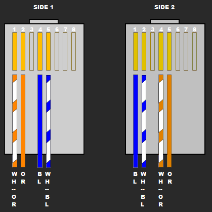
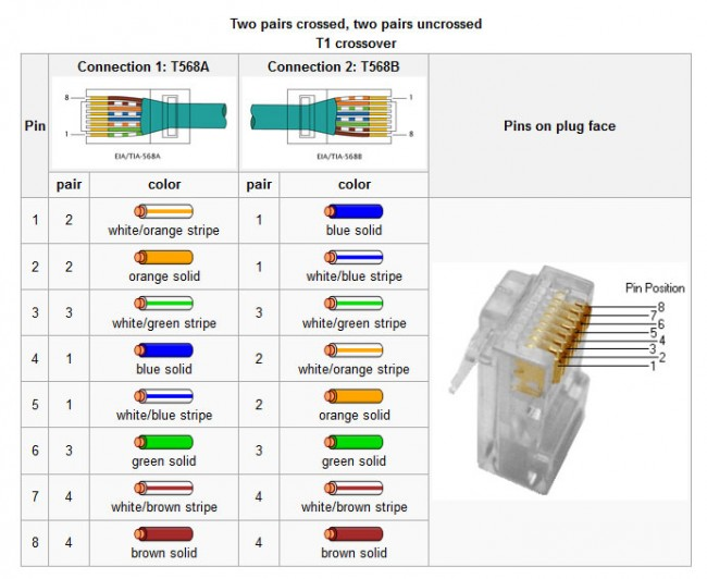
In some network applications, the equipment is so close together that a crossover. Using standard twisted pair cable and rj45 ends, make the following connections: Get it as soon as tomorrow, apr 8. The below diagram is not quite correct. It is most often used to connect two devices of the same type, e.g. 24.156.121.36 left the following message prior to the t1 crossover table in the other technologies section. An ethernet crossover cable, also known as a crossed cable, connects two ethernet network devices to each other. All of which can be. If you take a 568b ethernet cable its the orange pair and blue pair. The concept here is that you simply need to cross receive and send pairs so that send on one end goes to receive on the other. To make a t1 crossover cable you will need an rj45 crimping tool and at least one rj45 end. Look for a crossover cable color code with a wiring diagram for rj45 crossover cable or cross cable is a type of ethernet cable that is used to connect similar types of networking devices, in contrast to straight through cable which is used to connect different devices. Updated on april 23, 2020 doc navigation ← add service dependencies compile for a 64 bit os (for legacy versions prior to march 2010).
The t1/e1 crossover adapter converts any standard t1 or e1 modular cable to a crossover cable. Diagram for building a t1 crossover cable. Two computers (via their network interface controllers) or two switches to each other.by contrast, straight through patch cables are used to connect devices of different types, such as a computer to a network switch. These cables are also known as rj48c cables and can be purchased online or found in specialty stores like graybar or fry's. The two center pins on the rj11 will be used for a single line telephone.
10baset 100baset And Other Rj 45 A Tutorial from arcelect.com For industry references, see instead: Cat5 cabling guide on how to wire a straight pair, crossover, and t1 crossover cable. The t1/e1 crossover adapter converts any standard t1 or e1 modular cable to a crossover cable. The blue pair is the first pair to use. This is really simple to construct. It will also define the differences between and these standards. February 27, 2020 important this is a class a device and is intended for use in a light industrial environment. The below diagram is not quite correct.
Free shipping on orders over $25 shipped by amazon.
For the physical cable connection it is necessary to use a t1 crossover cable. Two for the transmit signal and two for the receive. The t1/e1 crossover adapter converts any standard t1 or e1 modular cable to a crossover cable. Below i show you what the connectors for each type of cross over would look like is using the full 4 pairs. The purpose of crossover cables. How to make a t1 crossover / pri cable. The below diagram is not quite correct. This is really simple to construct. For instance, you need cross cable if you are connecting. Although shielded t1 cable is the ideal, you will find that using a category 5 (cat5) patch cable will work just fine with out any issues. T1/e1/j1 rj48 cable diagram the following illustration provides the wiring connections for straight or crossover cables. The blue pair is the first pair to use. February 27, 2020 important this is a class a device and is intended for use in a light industrial environment.
Cat5 cabling guide on how to wire a straight pair, crossover, and t1 crossover cable. The below diagram is not quite correct. February 27, 2020 important this is a class a device and is intended for use in a light industrial environment. The two center pins on the rj11 will be used for a single line telephone. The purpose of crossover cables.
Cables And Wiring from kb.ic.uk Two computers (via their network interface controllers) or two switches to each other.by contrast, straight through patch cables are used to connect devices of different types, such as a computer to a network switch. Because a t1 uses pins 1,2,4,5 and a cat5 cable uses pins 1,2,3,6. So in this diagram we can see that pin 1 is connecting to pin 4 and pin 2 is connecting to pin 5. An ethernet crossover cable is a crossover cable for ethernet used to connect computing devices together directly. Used with a standard t1 or e1 modular cables, the superlooper can network two interfaces together to facilitate quick network testing. One end t568a, other end t568b (crossover cable). If using ethernet cable, look for the blue pair. The below diagram is not quite correct.
An ethernet crossover cable, also known as a crossed cable, connects two ethernet network devices to each other.
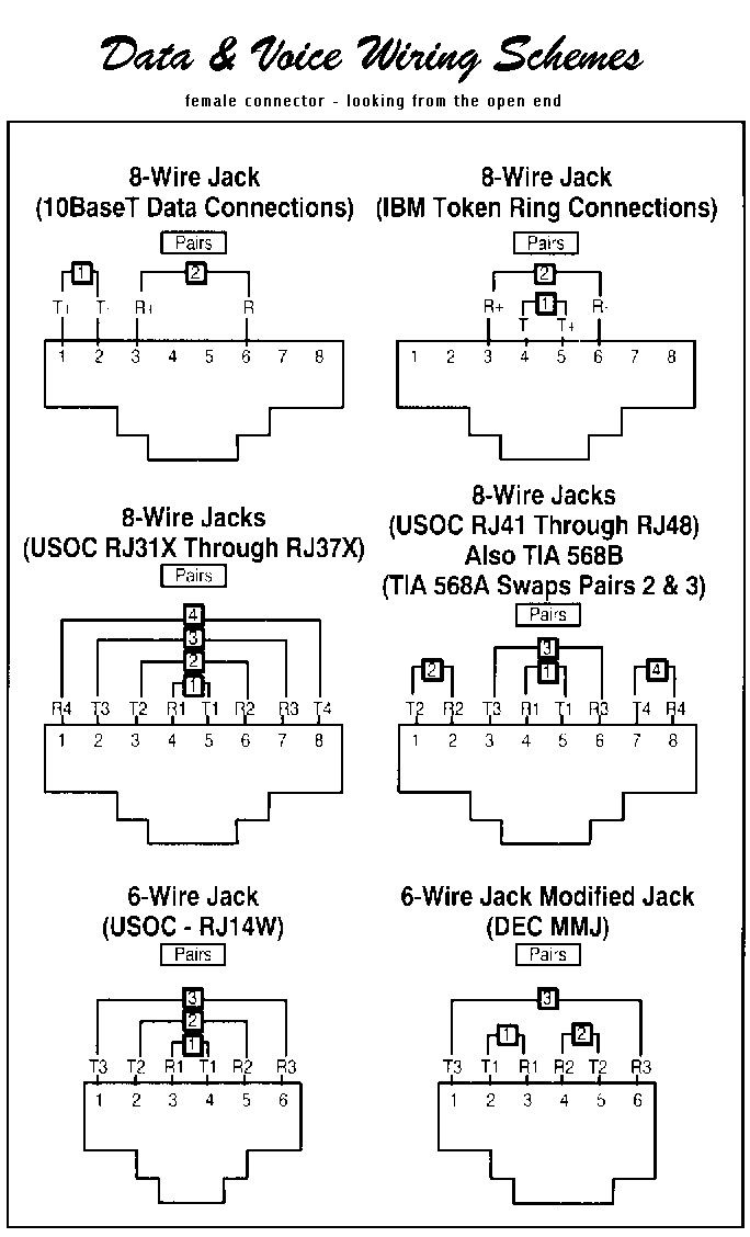
Two computers (via their network interface controllers) or two switches to each other.by contrast, straight through patch cables are used to connect devices of different types, such as a computer to a network switch. 24.156.121.36 left the following message prior to the t1 crossover table in the other technologies section. ~kvng 13:00, 9 may 2014 (utc) the following chart with diagrams is horribly confusing and full of mistakes. The below diagram is not quite correct. Cat5 cabling guide on how to wire a straight pair, crossover, and t1 crossover cable. It will also define the differences between and these standards. To make a t1 crossover cable you will need an rj45 crimping tool and at least one rj45 end. If you take a 568b ethernet cable its the orange pair and blue pair. For industry references, see instead: Pin 1 to pin 4 pin 2 to pin 5. This is really simple to construct. If using ethernet cable, look for the blue pair. The connectors shown at the top of the columns do not match the details down the column.