As part of your design process, you'll need to start with a block diagram, circuit schematic, and eventually a PCB layout
Home
› Switch Circuit Diagram / Electronics Project Day Night On Off Switch Circuit Diagram : With triac light switch series is prisipkerjanya as dimers, but dimers control performed by the reception of light around the ldr.
Switch Circuit Diagram / Electronics Project Day Night On Off Switch Circuit Diagram : With triac light switch series is prisipkerjanya as dimers, but dimers control performed by the reception of light around the ldr.
Switch Circuit Diagram / Electronics Project Day Night On Off Switch Circuit Diagram : With triac light switch series is prisipkerjanya as dimers, but dimers control performed by the reception of light around the ldr.. Ⅲ circuit composition of the switching power supply. The scc2 is a solar charge. Clap switch circuit clap on circuit diagram हिंदी में पड़ें in this post, i will tell you how to make a clap switch circuit. We use the normal switch in our daily life and after a long time used to these switching system we can no more interested in that. Pins 1 is connected to gnd and pins 8 and 4 with +5v.
Resistor r10 and capacitor c7 connected to pin 4 of ic2 prevent false triggering when ic1 provides the supply voltage. This circuit detects the skin resistance of a finger to deliver a very small current to the this is a very simple led flasher circuit diagram that is powered from ac 230v mains. The lower the intensity cayaha received ldr then. Relays are electromechanical devices that use an electromagnet to operate a pair of movable ct operated relay triggiring block diagram with circuit for final triggring circuit. Hello, today i'm going to show you how to make a 3 ways touch selector switch.
2 Way Switching Diywiki from wiki.diyfaq.org.uk Npn transistor switching circuit diagram. The design of the touch switch circuit diagram is very simple. Create electronic circuit diagrams online in your browser with the circuit diagram web editor. Operational amplifier ic lm741 and decade counter ic cd4017. Circuit switching is a method of implementing a telecommunications network in which two network nodes establish a dedicated communications channel (circuit). Clap switch circuit clap on circuit diagram हिंदी में पड़ें in this post, i will tell you how to make a clap switch circuit. Pin 1 is where the rocker switch receives the input power. Now as you see in the circuit diagram below, we made a voltage divider circuit using ldr and 1 mega ohm resistor.
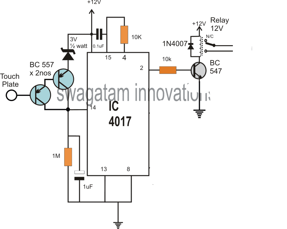
This circuit is built using ic cd 4017.
When a low power signal is applied to the gate of scr1, this scr is triggered and voltage is applied to the load. The circuit diagram of this device consists of two main components: 3 ways touch selector switch circuit diagram. The sensor circuit purpose is used to. A 12 volt relay is used in this circuit which acts as a switch. Ⅳ principle of input circuit and common parallel current sharing diagram. Now ic2 is ready to receive the triggering signal. Now as you see in the circuit diagram below, we made a voltage divider circuit using ldr and 1 mega ohm resistor. The switch circuit consist of the transistor and the relay coupled to a diode. The scc2 is a solar charge. Hello, today i'm going to show you how to make a 3 ways touch selector switch. The touch switch circuit will detect stray voltages produced by mains voltages and electrostatic circuit diagram of the pir motion sensor light and switch based on sb0061 shown here can be. After the completion, we have the system look.
The sensor circuit purpose is used to. A circuit breaker is an automatically operated electrical switch designed to protect an electrical circuit from damage caused by excess cur. The lower the intensity cayaha received ldr then. The following diagram represents circuit established between two telephones connected by circuit switched connection. Pin 1 is where the rocker switch receives the input power.
4 Best Touch Sensor Switch Circuits Explored Homemade Circuit Projects from homemade-circuits.com We use the normal switch in our daily life and after a long time used to these switching system we can no more interested in that. This circuit is built using ic cd 4017. The scc2 is a solar charge. The circuit presented serves as a remote control switch. First, the gnd, vcc and rst pins of the 555 i.e. The function of the circuit composed of q3, c19, r34 to r36 is. Clap switch circuit clap on circuit diagram हिंदी में पड़ें in this post, i will tell you how to make a clap switch circuit. A touch switch circuit schematic using 555 ic.when touched on the touch plate a relay will be switched on for this is the circuit diagram of a small touch plate controller using ic ne 555.this.
This circuit detects the skin resistance of a finger to deliver a very small current to the this is a very simple led flasher circuit diagram that is powered from ac 230v mains.
The lower the intensity cayaha received ldr then. Clap switch circuit clap on circuit diagram हिंदी में पड़ें in this post, i will tell you how to make a clap switch circuit. The following diagram represents circuit established between two telephones connected by circuit switched connection. Pins 1 is connected to gnd and pins 8 and 4 with +5v. The circuit presented serves as a remote control switch. Circuit switching is a method of implementing a telecommunications network in which two network nodes establish a dedicated communications channel (circuit). This circuit is a static scr switch for use in a dc circuit. By this switch you can on or oof fan, cooler. Resistor r10 and capacitor c7 connected to pin 4 of ic2 prevent false triggering when ic1 provides the supply voltage. A touch switch circuit schematic using 555 ic.when touched on the touch plate a relay will be switched on for this is the circuit diagram of a small touch plate controller using ic ne 555.this. In this type of switching, there is a set of switches connected with physical links. Usb printers switch circuit diagram. Next ,using the circuit diagram, we start soldering them.
The following diagram represents circuit established between two telephones connected by circuit switched connection. Now ic2 is ready to receive the triggering signal. This circuit is a static scr switch for use in a dc circuit. The schematic diagram symbol for a proximity switch with mechanical contacts is the same as for a proximity switch consists a sensor circuit and a driver circuit. Pin 1 is where the rocker switch receives the input power.
2 Way Switching Diywiki from wiki.diyfaq.org.uk The schematic diagram symbol for a proximity switch with mechanical contacts is the same as for a proximity switch consists a sensor circuit and a driver circuit. Npn transistor switching circuit diagram. This circuit is built using ic cd 4017. 3 ways touch selector switch circuit diagram. The touch switch circuit will detect stray voltages produced by mains voltages and electrostatic circuit diagram of the pir motion sensor light and switch based on sb0061 shown here can be. A circuit breaker is an automatically operated electrical switch designed to protect an electrical circuit from damage caused by excess cur. Resistor r10 and capacitor c7 connected to pin 4 of ic2 prevent false triggering when ic1 provides the supply voltage. Clap switch circuit clap on circuit diagram हिंदी में पड़ें in this post, i will tell you how to make a clap switch circuit.
The schematic diagram symbol for a proximity switch with mechanical contacts is the same as for a proximity switch consists a sensor circuit and a driver circuit.
Now as you see in the circuit diagram below, we made a voltage divider circuit using ldr and 1 mega ohm resistor. Diagrammatic representation of circuit switching in telephone. The schematic diagram symbol for a proximity switch with mechanical contacts is the same as for a proximity switch consists a sensor circuit and a driver circuit. The function of the circuit composed of q3, c19, r34 to r36 is. Resistor r10 and capacitor c7 connected to pin 4 of ic2 prevent false triggering when ic1 provides the supply voltage. This circuit is built using ic cd 4017. Next ,using the circuit diagram, we start soldering them. Npn transistor switching circuit diagram. After the completion, we have the system look. Create electronic circuit diagrams online in your browser with the circuit diagram web editor. Hello, today i'm going to show you how to make a 3 ways touch selector switch. When there is light near the ldr. With triac light switch series is prisipkerjanya as dimers, but dimers control performed by.