As part of your design process, you'll need to start with a block diagram, circuit schematic, and eventually a PCB layout
Home
› Electric Trailer Brakes Wiring - Electric Brake Control Wiring / From turn signals to tail lights, we have all the wiring connections for your truck and towing needs.
Electric Trailer Brakes Wiring - Electric Brake Control Wiring / From turn signals to tail lights, we have all the wiring connections for your truck and towing needs.
Electric Trailer Brakes Wiring - Electric Brake Control Wiring / From turn signals to tail lights, we have all the wiring connections for your truck and towing needs.. The blue (brake output) wire must be connected to the trailer connector's brake wire. Refer to the diagram below to locate yours. A wiring diagram is a simplified conventional photographic depiction of an electric circuit. The amps will be higher if using a tandem axle or triple axle trailer. It ought not be carrying heavy loads during the journey.
It shows the components of the circuit as streamlined shapes, and the power and also signal connections in between the devices. Curt 51500 electric trailer brake controller wiring kit. The blue (brake output) wire must be connected to the trailer connector's brake wire. In this guide we will unpack how a trailer brake controller works and the steps involved in how to use a brake controller while towing with trailer brakes. * always test wires for function and wire accordingly.
Trailer Wiring Diagrams For Single Axle Trailers And Tandem Axle Trailers from i2.wp.com Another way to identify between the two is the bottom spring. It does not matter which wire is used for power or ground because they are not polarized. Curt 51500 electric trailer brake controller wiring kit. By law, trailer lighting must be connected into the tow vehicle's wiring system to provide trailer running lights, turn signals and brake lights. For these systems to operate properly, the trailer wiring end plug on the trailer must match the wiring pattern of the mating plug on the tow vehicle. There are wires extending from the switch and using a circuit tester, you can find the wire that has power when the brake pedal is pressed. Variety of trailer breakaway wiring schematic. The fsa brakes will have a wire that will run from about 9 o'clock to 1 o'clock.
It shows the components of the circuit as streamlined shapes, and the power and also signal connections in between the devices.
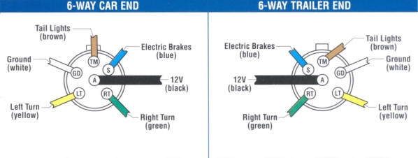
By law, trailer lighting must be connected into the tow vehicle's wiring system to provide trailer running lights, turn signals and brake lights. This is only slightly under a maximum brake load of 16 amps. A wiring diagram is a streamlined conventional pictorial representation of an electric circuit. Variety of trailer breakaway wiring schematic. The location of your vehicle's factory wiring harness may vary. Wellborn assortment of electric trailer brake wiring schematic. The amps will be higher if using a tandem axle or triple axle trailer. From turn signals to tail lights, we have all the wiring connections for your truck and towing needs. A wiring diagram is a simplified conventional photographic depiction of an electric circuit. The black wire is the power supply line to the brake control. It does not matter which wire is used for power or ground because they are not polarized. The red (stoplight) wire must be connected to the cold side of the brake pedal stoplight switch. Rt right turn/brake light brown lt left turn/brake light red s trailer electric brakes blue gd ground white a accessory yellow this is the most common (standard) wiring scheme for rv plugs and the one used by major auto manufacturers today.
If a trailer has brakes, then it needs a connector with at least 5 pins. One wire is for 12 volt power to the brake magnets and the other wire should be grounded either to the trailer frame or to the main trailer ground wire. Fenders, couplers, lights & more. * always test wires for function and wire accordingly. It would not overload the wire and cause excess heating as 16 gauge wire has a recommended allowable ampacity of 15 amps.
Trailer Wiring from horsetrailerworld.com Connect your blue wire (which is the one that controls brakes) to the multimeter with an ammeter setting between the brake controller and trailer connector. Another way to identify between the two is the bottom spring. With this kind of an illustrative manual, you are going to be capable of troubleshoot, stop, and total your assignments with ease. Using a brake controller while towing a trailer involves setting up the controller, adjusting to the load size, adjusting braking sensitivity, manually activating the trailer brakes and possibly choosing a few personal settings. Splice down line from the switch; December 6, 2019 by larry a. How electric trailer brakes work. Trailer electrical connectors come in a variety of shapes and sizes.
Each of your new brakes will have two wires for the brake magnet.
Variety of trailer breakaway wiring schematic. It ought not be carrying heavy loads during the journey. Trailer wiring diagrams trailer wiring connectors various connectors are available from four to seven pins that allow for the transfer of power for the lighting as well as auxiliary functions such as an electric trailer brake controller, backup lights, or a 12v power supply for a winch or interior trailer lights. Wellborn assortment of electric trailer brake wiring schematic. It ought not be carrying significant loads through the trip. For these systems to operate properly, the trailer wiring end plug on the trailer must match the wiring pattern of the mating plug on the tow vehicle. There are wires extending from the switch and using a circuit tester, you can find the wire that has power when the brake pedal is pressed. With this kind of an illustrative manual, you are going to be capable of troubleshoot, stop, and total your assignments with ease. Sealed electric wire connectors for brake applications, 3m brand (5 pack) sku: One wire is for 12 volt power to the brake magnets and the other wire should be grounded either to the trailer frame or to the main trailer ground wire. December 6, 2019 by larry a. It reveals the parts of the circuit as streamlined forms, as well as the power and signal connections in between the gadgets. 4.5 out of 5 stars 93.
The red (stoplight) wire must be connected to the cold side of the brake pedal stoplight switch. Electric brake systems consist of components mounted both on the tow vehicle and the trailer. Trailer electrical connectors come in a variety of shapes and sizes. Sealed electric wire connectors for brake applications, 3m brand (5 pack) sku: If you need to connect two different wiring systems, check out our selection of connectors and converters.
Universal Installation Kit For Trailer Brake Controller 7 Way Rv And 4 Way Flat 10 Gauge Wires E Trailer Trailer Plans Installation from i.pinimg.com From turn signals to tail lights, we have all the wiring connections for your truck and towing needs. Sealed electric wire connectors for brake applications, 3m brand (5 pack) sku: The location of your vehicle's factory wiring harness may vary. Another way to identify between the two is the bottom spring. Get it as soon as tue, jun 1. All the parts needed to repair and maintain your trailer including electric brake wiring & battery, brake electric controller, brake electric controller from trailerpartsdepot.com. This short video is about trailer brakes, electric brakes and wiring. The amps will be higher if using a tandem axle or triple axle trailer.
From turn signals to tail lights, we have all the wiring connections for your truck and towing needs.
One wire is for 12 volt power to the brake magnets and the other wire should be grounded either to the trailer frame or to the main trailer ground wire. Do not disturb the position of the switch. The location of your vehicle's factory wiring harness may vary. It ought not be carrying significant loads through the trip. The amps will be higher if using a tandem axle or triple axle trailer. Sealed electric wire connectors for brake applications, 3m brand (5 pack) sku: 4.5 out of 5 stars 93. Ensure it is sealed off and cannot create a short circuit with any other wire or the chassis. There is a very basic wiring electric trailer brakes diagram. The fsa brakes will have a wire that will run from about 9 o'clock to 1 o'clock. For these systems to operate properly, the trailer wiring end plug on the trailer must match the wiring pattern of the mating plug on the tow vehicle. It reveals the parts of the circuit as streamlined forms, as well as the power and signal connections in between the gadgets. A wiring diagram is a streamlined conventional pictorial representation of an electric circuit.