Trailer Wiring Colors - Trailer Wiring Diagrams North Texas Trailers Fort Worth / Trailer lights, trailer wiring harness kit & more.. Touch device users, explore by touch or with swipe gestures. The four wires control the turn signals, brake lights and taillights or running lights. They also provide a wire for a ground connection. Every wiring diagram is different from the next, and they will be different from the next one. This is also a requirement of the national electrical code (nfpa 70), article 406 interior width (cm):
It should show all the parts, their color, and their significance to the overall process. A wiring diagram is a simplified standard photographic depiction of an electric circuit. You must check the trailer manual to see if the wiring is correct, but normally the white wire is called the ground wire, while the brown wire is used for tail lights. Let's see what types of connectors the trailer light wiring industry uses today. Use a circuit tester to verify connections.
Dodge Ram 2500 Trailer Wiring Wiring Diagram Link Initial from i0.wp.com Remember that yellow has a l in it so that is the left side brake/turn signal and green has a r in it so that is the right side brake/turn signal. Can also be used as custom wiring on trailers with 3 light/wire systems. They also provide a wire for a ground connection. Use a circuit tester to verify connections. Manufacturers have changed the wire colors on vehicles. The four wires control the turn signals, brake lights and taillights or running lights. You must check the trailer manual to see if the wiring is correct, but normally the white wire is called the ground wire, while the brown wire is used for tail lights. This dodge ram 7 pin trailer wiring diagram model is more acceptable for sophisticated trailers and rvs.
Each wire shown in the diagrams contains a code (fig.
The worst that usually happens with screwy trailer wiring is a blown fuse on the tow vehicle—or something wacky, like reversed turn signals or blinking brake lights. A thin coat of grease will help prevent copper oxide from building up. A wiring diagram is a simplified standard photographic depiction of an electric circuit. Trailer wiring diagrams trailer wiring connectors various connectors are available from four to seven pins that allow for the transfer of power for the lighting as well as. Use on a small motorcycle trailer, snowmobile trailer or utility trailer. This is also a requirement of the national electrical code (nfpa 70), article 406 interior width (cm): The four wires control the turn signals, brake lights and taillights or running lights. Use a circuit tester to verify connections. When autocomplete results are available use up and down arrows to review and enter to select. 3/4 inch by 1 inch 6 way rectangle connectors right turn signal (green), left turn signal (yellow), taillight (brown), ground (white). There are many reasons why a person might need a wiring diagram. You must check the trailer manual to see if the wiring is correct, but normally the white wire is called the ground wire, while the brown wire is used for tail lights. 6 way plug wiring diagr am standard wiring* post purpose wire color tm park lights brown gd ground black (or white) s trailer brakes blue lt left turn/brake light yellow rt right turn/brake light green a accessory red the most common variances on this diagram will be the (blue/brake) & (red/acc.) wires will be inverted.
It shows the parts of the circuit as simplified shapes, as well as the power as well as signal connections in between the tools. The ground wire should be large enough to handle the entire load, do not depend on grounding through the ball. Clearly labeled wiring helps savvy owners with diy. A wiring diagram is a simplified standard photographic depiction of an electric circuit. The red and blue wire can be used for brake control or auxiliary.
Australian Trailer Plug And Socket Pinout Wiring 7 Pin Flat And Round Find Thingy from findthingy.com This is also a requirement of the national electrical code (nfpa 70), article 406 interior width (cm): Clearly labeled wiring helps savvy owners with diy. Trailer wiring connectors various connectors are available from four to seven pins that allow for the transfer of power for the lighting as well as auxiliary functions such as an electric trailer brake controller, backup lights, or a 12v power supply for a winch or interior trailer lights. Remember that yellow has a l in it so that is the left side brake/turn signal and green has a r in it so that is the right side brake/turn signal. The worst that usually happens with screwy trailer wiring is a blown fuse on the tow vehicle—or something wacky, like reversed turn signals or blinking brake lights. 1) which identifies the main circuit, part of the main circuit, gauge of wire, and color. 3/4 inch by 1 inch 6 way rectangle connectors right turn signal (green), left turn signal (yellow), taillight (brown), ground (white). Yellow and green are for left and right turns and braking.
When autocomplete results are available use up and down arrows to review and enter to select.
A skilled electrical designer will be able to produce a diagram that is clear and to the point. Every wiring diagram is different from the next, and they will be different from the next one. Yellow and green are for left and right turns and braking. Use a circuit tester to verify connections. 6 way plug wiring diagr am standard wiring* post purpose wire color tm park lights brown gd ground black (or white) s trailer brakes blue lt left turn/brake light yellow rt right turn/brake light green a accessory red the most common variances on this diagram will be the (blue/brake) & (red/acc.) wires will be inverted. Make sure your ground wire, which is typically white, is securely attached to the frame on both the truck and trailer side. This dodge ram 7 pin trailer wiring diagram model is more acceptable for sophisticated trailers and rvs. 4 pin trailer wiring color code. Trailers are required to have at least running lights, turn signals and brake lights. The red and blue wire can be used for brake control or auxiliary. It shows the parts of the circuit as simplified shapes, as well as the power as well as signal connections in between the tools. This is a long list, press control+f on your keyboard to quickly 12. 4.6 out of 5 stars.
Standard color code for wiring simple 4 wire trailer lighting. This is also a requirement of the national electrical code (nfpa 70), article 406 interior width (cm): Let's see what types of connectors the trailer light wiring industry uses today. They also provide a wire for a ground connection. Use a circuit tester to verify connections.
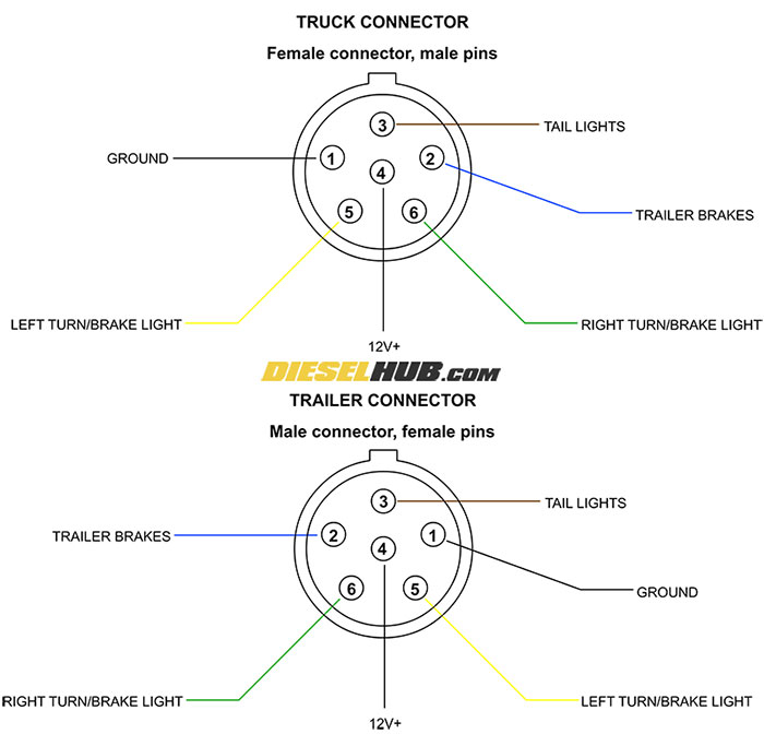
Trailer Connector Pinout Diagrams 4 6 7 Pin Connectors from www.dieselhub.com Variety of dodge trailer wiring diagram 7 pin. A skilled electrical designer will be able to produce a diagram that is clear and to the point. This chart is a typical guide, wire colors may vary based on manufacturers. Trailer wiring diagrams trailer wiring connectors various connectors are available from four to seven pins that allow for the transfer of power for the lighting as well as. 6 way plug wiring diagr am standard wiring* post purpose wire color tm park lights brown gd ground black (or white) s trailer brakes blue lt left turn/brake light yellow rt right turn/brake light green a accessory red the most common variances on this diagram will be the (blue/brake) & (red/acc.) wires will be inverted. What is a 7 way trailer connector? Make sure your ground wire, which is typically white, is securely attached to the frame on both the truck and trailer side. Remember that yellow has a l in it so that is the left side brake/turn signal and green has a r in it so that is the right side brake/turn signal.
What is a 7 way trailer connector?
The ground wire should be large enough to handle the entire load, do not depend on grounding through the ball. Every wiring diagram is different from the next, and they will be different from the next one. 12n (normal) electrics wiring diagram for the exterior lighting on a trailer or caravan from western towing 1) which identifies the main circuit, part of the main circuit, gauge of wire, and color. Manufacturers have changed the wire colors on vehicles. Can also be used as custom wiring on trailers with 3 light/wire systems. A thin coat of grease will help prevent copper oxide from building up. Trailer wiring tips brought to you by etrailer.com for all your trailer wiring needs. You must check the trailer manual to see if the wiring is correct, but normally the white wire is called the ground wire, while the brown wire is used for tail lights. In 20 seconds you can become part of the worlds largest and oldest community discussing general motors, chevrolet and gmc branded pickups, crossovers, and suvs. A wiring diagram is a simplified standard photographic depiction of an electric circuit. Trailers are required to have at least running lights, turn signals and brake lights. If your vehicle is not equipped with a working trailer wiring harness, there are a number of different solutions to provide the perfect fit for.